I've done a 50/60Hz mod because PAL CDi's basically suck because some (most?) games don't show in full screen.
Something you may want to know first. On 60Hz mode you will only get colour with a RGB SCART cable, if you use composite vídeo, you will get a black & white picture even if your TV supports NTSC.
I'm guessing it's because american counter parts use a different oscillator frequency, so when switching to NTSC mode will give you a colour burst frequency other than the 3.58MHz that the TV expects to receive to display colour. Once again if using RGB you'll have ful colour on both modes.
OK, now for the good part: (I used some images and info from this site: http://www.cdiemu.org/ I hope the author doesn't mind)
As far as connections go, this is what you'll have to do:
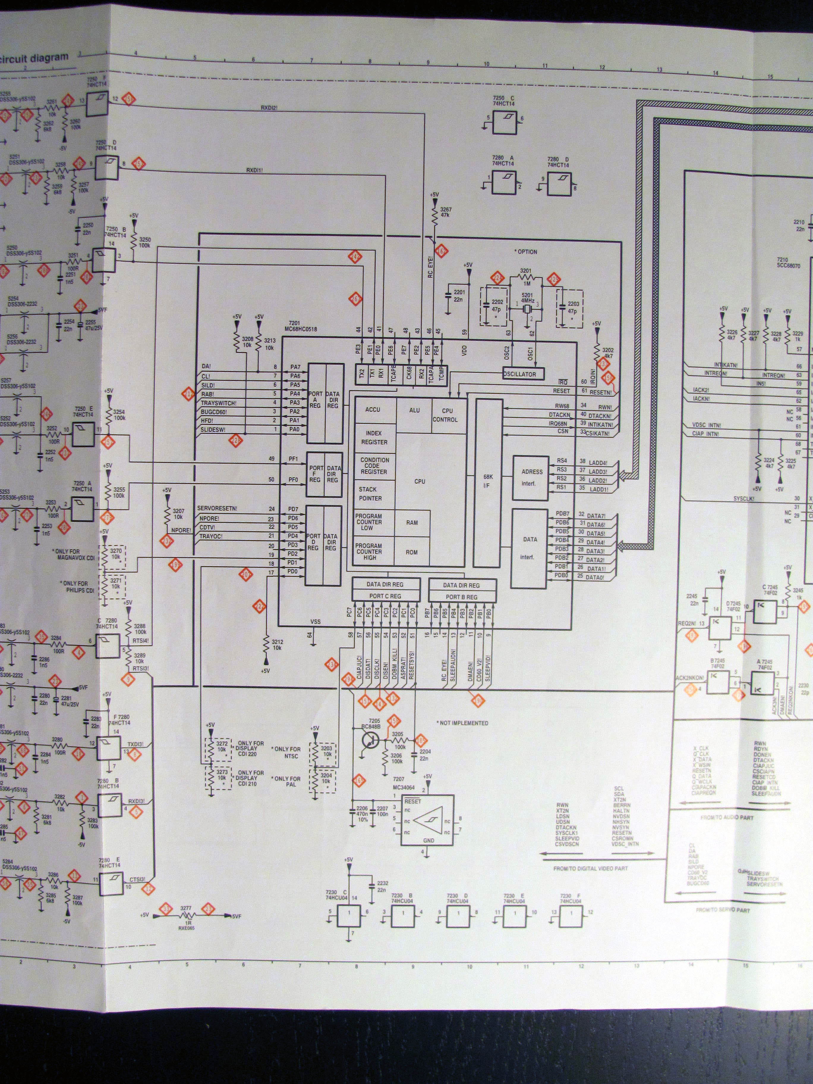
Remove the resistor shown inside the circle:

Start by connecting the pads with some length of wire as shown to a single pole double throw switch adding a 10Kohm resistor on the center leg of the switch.

Thats basically it, find a location for the switch, and use your imagination on where to place it, here's a few photos on how I did mine, hope you like it.